
This is the follow-up of my previous post on the installation of the ACI Openstack integration plugin (OpFlex mode) in my lab. In this blog post, we will take a step back and discuss why we would want to integrate ACI with OpenStack in the first place, the benefits of the integration (especially OpFlex mode), the different integration modes (ML2 vs. GBP, OpFlex vs. non OpFlex) and the decision to choose one.
You may also find very good details on this topic covered in Cisco ACI Unified Plug-in for OpenStack Architectural Overview document. I am not trying to make a full clone of the whitepaper here, but will summarize some key points and provide demonstrations specific for our previous lab setup with some packet capture to illustrate the networking features that we have discussed.
Why ACI and OpenStack?
First, we need to mention Cisco’s ACI Anywhere vision, where ACI is positioned to be a single-pane-of-glass management for both on-premise infrastructure (virtualized or physical workload) and public clouds. OpenStack, one of the most popular virtualized infrastructures, can be integrated with ACI with other virtualized workload on the same DC network fabric. ACI has the capabilities to integrate other virtualized domains such as VMWare ESXi, Microsoft SCVMM, RHEV, container platforms (OpenShift, Cloud Foundary, Kubernetes) as well as cloud providers (AWS, Azure).
Secondly, the standard OpenStack Neutron deployment has some limitations, and Cisco ACI-OpenStack integration offers improvements to solve them:
- Support for distributed L3 services and optimizations: full Neutron node datapath can be replaced by ACI, distributed DHCP and metadata, Distributed NAT and floating IP address (in OpFlex mode)
- Fully distributed Layer 2 using ACI anycast/pervasive gateway.
- Automatic VXLAN tunnel creation on hardware ToR (mapping from VLAN/VXLAN into fabric tunnels).
- Fast data plane support (SR-IOV/OVS-DPDK) (non-OpFlex mode with VLAN encapsulation).
- Same standard OpenStack Neutron call, underlay network taken care by ACI.
- Visibility of virtualized workload on OpenStack (in OpFlex mode) on ACI.
- Operation and telemetry: tenant health score, capacity planning, etc.
Integration modes and networking models of the plugin
This section will provide some summary about different integration modes (OpFlex/non-OpFlex) and networking models (ML2/GBP) of the ACI OpenStack plugin, so you can decide what options suit you best.
OpFlex vs. Non-OpFlex integration modes
In OpFlex mode, APIC control the upstream OVS running on compute nodes using OpFlex protocol. This requires the installation of OpFlex agent on the compute nodes. Choose this mode if you want:
- An OpenStack VMM domain created on ACI with the compute nodes connectivity shown and OpenStack instances (VM) visibility on ACI.
- Neutron data path replaced by OVS and ACI with per-host distributed routing, DHCP optimization, metadata optimization, distributed NAT and Floating IP enforcement
- VXLAN or VLAN encapsulation from the compute hosts to the ACI leaf switch ports
In non-OpFlex mode, APIC only programs the physical fabric (network connectivity) and treats OpenStack tenant traffic as part of the Physical Domain (PhysDom) integration. Choose this mode if you want:
- Data plane acceleration such as OVS-DPDK or SR-IOV (only VLAN encapsulation)
- ACI to provide L2/L3 forwarding on the ACI with anycast gateway feature but no Cisco agents needed on the compute nodes
ML2 or GBP networking models
The networking model defines the mapping between OpenStack network objects with APIC objects.
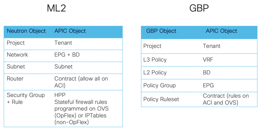
Choose ML2 if you want a “network-centric” approach:
- Standard and familiar way of creating networks
- Using existing Horizon GUI/Neutron API/CLI or any Heat template will transparently work.
Choose GBP if you prefer an “application-centric” approach:
- OpenStack objects closely mapped to ACI policy model
- Security groups created as ACI contracts with rules and OVS rules. They are visible on ACI.
The ACI integration plugin is Unified, meaning it supports both ML2 and GBP. We can even mix ML2 and GBP in the same OpenStack deployment, but each project can use only one or the other.
My lab setup (OpFlex mode-VXLAN encapsulation-ML2 model)
In my lab setup from the previous post, I installed the integration plugin in OpFlex/ML2 mode with VXLAN encapsulation. We will observe the above-mentioned characteristics and benefits of the integration plugin in this lab: the ACI objects that the plugin creates, the distributed routing feature, the DHCP and metadata optimization, and the distributed NAT and floating IP enforcement.
Lab setup script
The whole lab can be brought up by running the below openstack.sh script (this assumes you have created the needed instance flavor, the glance cirros-0.4.0 image, and have got the OpenStack RC environment file). It also makes use of the create_rc.sh script to create RC environment file for each project we create.
# Create project RED and switch to that project
source adminrc.sh
red_project_id=`openstack project create --description "Tenant RED" --domain "admin_domain" red | grep ' id' | awk {'print $4'}`
openstack role add --project red --user admin admin
./create_rc.sh red $red_project_id
source redrc.sh

# Create the neutron network objects in project RED
openstack network create red-net01
openstack subnet create --network red-net01 --gateway 192.168.1.1 --subnet-range 192.168.1.0/24 red-subnet01
openstack network create red-net02
openstack subnet create --network red-net02 --gateway 192.168.2.1 --subnet-range 192.168.2.0/24 red-subnet02

openstack router create red-router01
openstack router add subnet red-router01 red-subnet01
openstack router add subnet red-router01 red-subnet02
# Spin up the instances in the corresponding networks
openstack server create --image cirros-0.4.0 --flavor m1.extra_tiny --availability-zone az-1 --network red-net01 red-vm1-net01-az1
openstack server create --image cirros-0.4.0 --flavor m1.extra_tiny --availability-zone az-1 --network red-net01 red-vm2-net01-az1
openstack server create --image cirros-0.4.0 --flavor m1.extra_tiny --availability-zone az-1 --network red-net02 red-vm3-net02-az1
openstack server create --image cirros-0.4.0 --flavor m1.extra_tiny --availability-zone az-2 --network red-net01 red-vm4-net01-az2
openstack server create --image cirros-0.4.0 --flavor m1.extra_tiny --availability-zone az-2 --network red-net02 red-vm5-net02-az2
openstack server create --image cirros-0.4.0 --flavor m1.extra_tiny --availability-zone az-2 --network red-net02 red-vm6-net02-az2

# Create some isolated networks and spin up servers in those networks
openstack network create red-isolated-net03
openstack subnet create --network red-isolated-net03 --gateway 192.168.3.1 --subnet-range 192.168.3.0/24 red-isolated-subnet03
openstack server create --image cirros-0.4.0 --flavor m1.extra_tiny --availability-zone az-1 --network red-isolated-net03 red-vm7-net03-az1

openstack network create red-isolated-net04
openstack subnet create --network red-isolated-net04 --gateway 192.168.4.1 --subnet-range 192.168.4.0/24 red-isolated-subnet04
openstack server create --image cirros-0.4.0 --flavor m1.extra_tiny --availability-zone az-1 --network red-isolated-net04 red-vm8-net04-az1

# Create project BLUE and switch to that project
source adminrc.sh
blue_project_id=`openstack project create --description "Tenant BLUE" --domain "admin_domain" blue | grep ' id' | awk {'print $4'}`
openstack role add --project blue --user admin admin
./create_rc.sh blue $blue_project_id
source bluerc.sh

# Create the neutron network objects in project BLUE
openstack network create blue-net01
openstack subnet create --network blue-net01 --gateway 192.168.1.1 --subnet-range 192.168.1.0/24 blue-subnet01

openstack router create blue-router01
openstack router add subnet blue-router01 blue-subnet01
openstack server create --image cirros-0.4.0 --flavor m1.extra_tiny --availability-zone az-1 --network blue-net01 blue-vm1-net01-az1

# Create an isolated network and spin up an instance in that network
openstack network create blue-isolated-net02
openstack subnet create --network blue-isolated-net02 --gateway 192.168.2.1 --subnet-range 192.168.2.0/24 blue-isolated-subnet02
openstack server create --image cirros-0.4.0 --flavor m1.extra_tiny --availability-zone az-1 --network blue-isolated-net02 blue-vm8-net02-az1

## Create external network
neutron net-create external-net-common --router:external --apic:distinguished_names type=dict ExternalNetwork=uni/tn-common/out-dc-out/instP-dc-out-ext-epg
neutron subnet-create external-net-common 172.17.0.0/24 --name ext-subnet-common --disable-dhcp --gateway 172.17.0.1 --apic:snat_host_pool True
neutron subnet-create external-net-common 172.18.0.0/24 --name ext-subnet-FIP --allocation-pool start=172.18.0.10,end=172.18.0.100 --disable-dhcp --gateway 172.18.0.1
openstack router set --external-gateway external-net-common red-router01
The lab scenario brought up by the script looks like following (click for full size image):
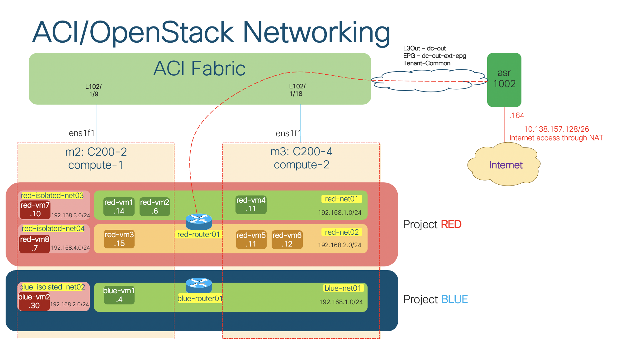
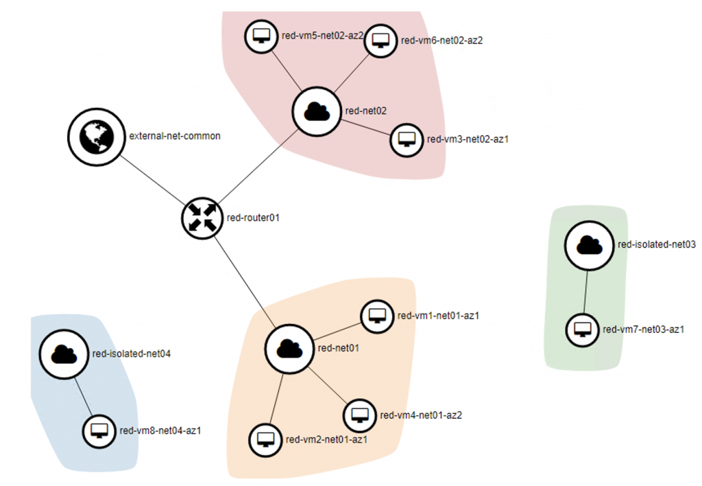
The network topology of the project Red shown on Horizon dashboard:
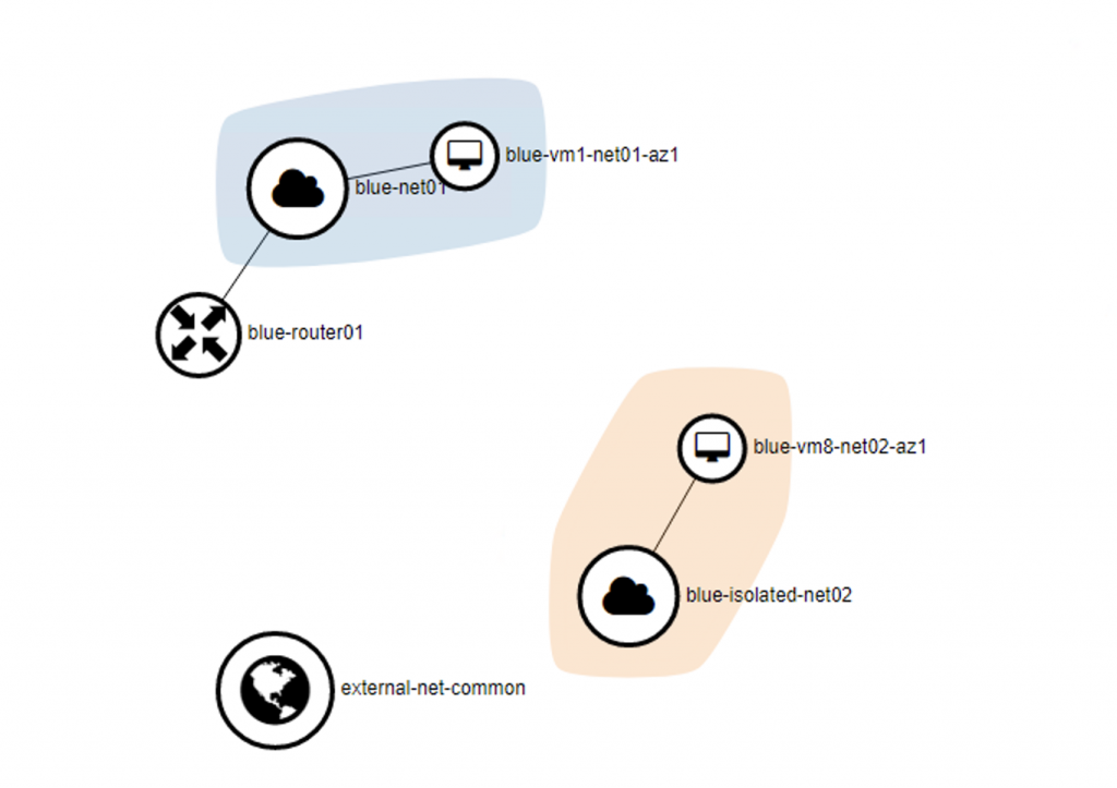
The network topology of the project Blue shown on Horizon dashboard:
ACI objects created by the plugin
As we used the ML2 networking models for the created OpenStack tenants, we can observe the mappings between the Neutron objects with the APIC objects.
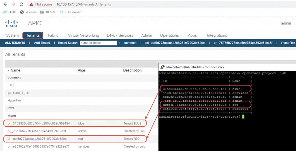
Tenants
A tenant will be created on ACI for each project created in OpenStack. The tenant name will be prj_<project_id> with the alias equals to project name.
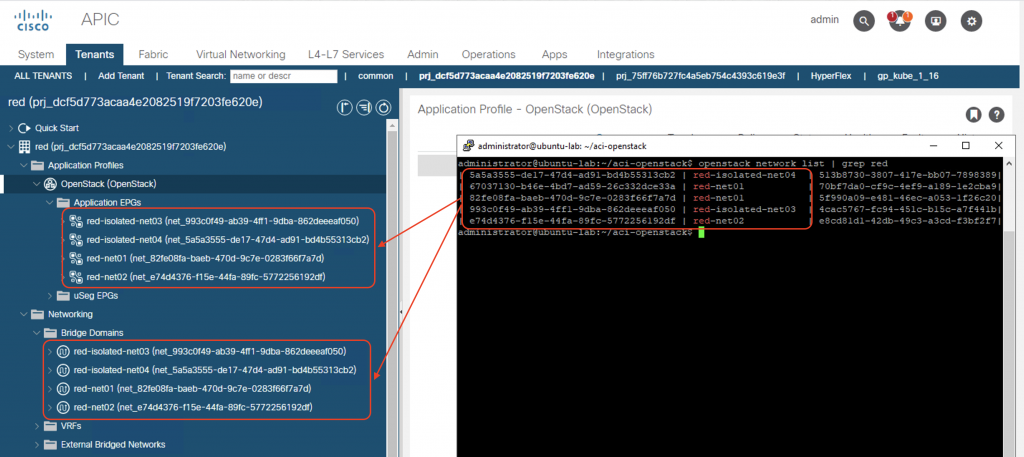
Networks
For each network in OpenStack, an EPG and a BD will be created on ACI. Screenshot below shows the mapping of the routed network red-net01 in project red with ACI constructs:
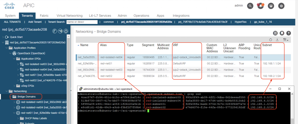
Subnets and VRF mapping on BDs
The corresponding subnets for the Neutron networks will be created as Subnets in the ACI Bridge Domains. Notice that the subnet IP will only be configured on the Neutron networks which have the router interface attached (routed network). All routed subnets will be mapped to the DefaultVRF of the tenant, while the isolated/unrouted subnets will all be mapped to <openstack_integration_id>_UnroutedVRF, in this case juju2-ostack_UnroutedVRF, within tenant common.
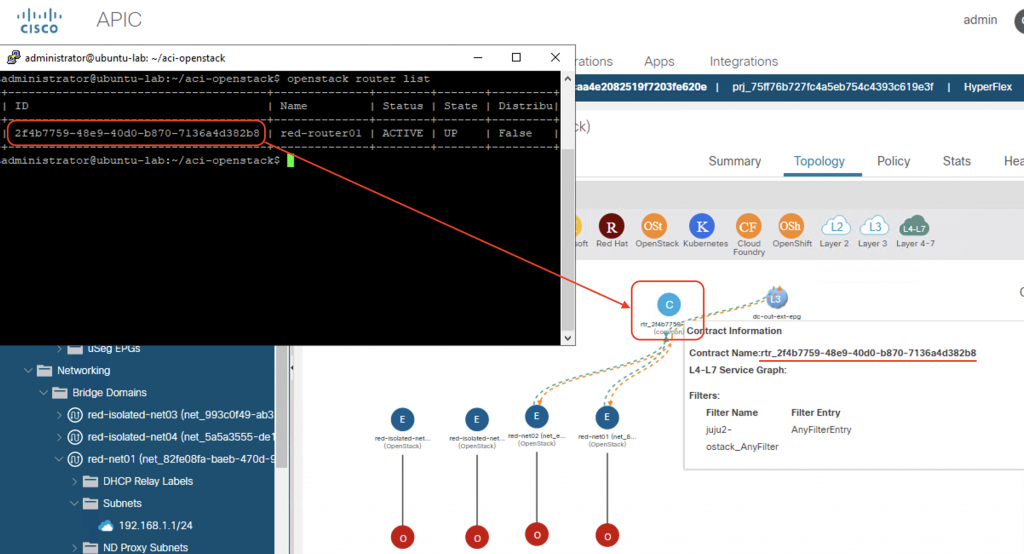
Router
For each router connecting Neutron subnets in OpenStack, a contract is defined on ACI with name rtr_<router_id> that allow all traffic. Notice that ACI fabric configures the IP subnets on the Bridge Domain only when a router is defined. That is why we do not see the subnet information (192.168.3.0/24 and 192.168.4.0/24) on the Bridge Domains that represent the isolated networks in the previous screenshot.
Security groups
As the contract on ACI will allow all traffic between subnets, the security rules will be defined as OVS rules on the compute nodes. We will observe these rules when we create a new security group and do the flow dumps on the integration bridge in the next section.
Distributed routing function
In OpFlex mode, the Neutron data path is completely replaced by the distributed routing function enforced by OVS at the compute node level.
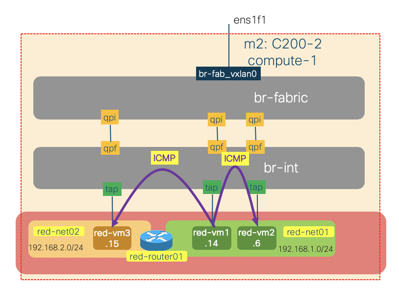
Traffic between instances on the same compute node
The traffic within a compute node (intra- or inter- subnets) will always be locally switched or routed by OVS. To illustrate this, we will issue some ICMP traffic on the red-vm1-net01-az1 instance (192.168.1.14) to red-vm2-net01-az1(192.168.1.6 – same subnet) and red-vm3-net02-az1 (192.168.2.15 – different subnet) and do some packet sniffing on the br-int and br-fabric of the compute-1 node.
We create the OVS port mirrors on the br-int and br-fabric:
sudo ip link add name br-int-snooper0 type dummy
sudo ip link set dev br-int-snooper0 up
sudo ovs-vsctl add-port br-int br-int-snooper0
sudo ovs-vsctl -- set Bridge br-int mirrors=@m -- --id=@br-int-snooper0 get Port br-int-snooper0 -- --id=@br-int get Port br-int -- --id=@m create Mirror name=mymirror1 select-dst-port=@br-int select-src-port=@br-int output-port=@br-int-snooper0 select_all=1

sudo ip link add name br-fab-snooper0 type dummy
sudo ip link set dev br-fab-snooper0 up
sudo ovs-vsctl add-port br-fabric br-fab-snooper0
sudo ovs-vsctl -- set Bridge br-fabric mirrors=@m -- --id=@br-fab-snooper0 get Port br-fab-snooper0 -- --id=@br-fabric get Port br-fabric -- --id=@m create Mirror name=mymirror1 select-dst-port=@br-fabric select-src-port=@br-fabric output-port=@br-fab-snooper0 select_all=1
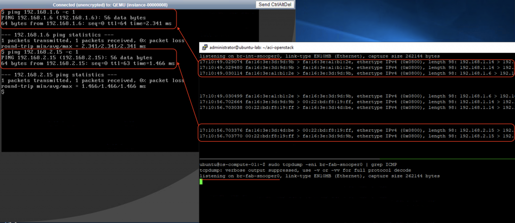
Then we capture the packets on the snooper interfaces as we issue the ping command on the vm1 instance.
sudo tcpdump -eni br-int-snooper0 | grep ICMP
sudo tcpdump -eni br-fab-snooper0 | grep ICMP
As we might expect there is no ICMP traffic seen on the br-fabric bridge (going out of the node). All the ICMP traffic are switched or routed locally by br-int.
Traffic between instances across different compute nodes
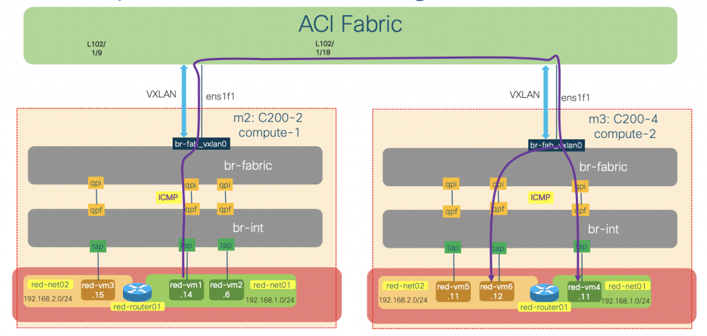
The traffic between instances on different compute nodes will traverse both br-int and br-fabric bridges. The br-fabric bridge will handle the encapsulation and routing of the traffic towards ACI fabric, which in turn route the packet within ACI fabric to the other compute node.
To illustrate this behavior, we will issue some ICMP traffic on the red-vm1-net01-az1 instance (192.168.1.14) to red-vm4-net01-az2(192.168.1.11 – same subnet) and red-vm6-net02-az2 (192.168.2.12 – different subnet) and do some packet sniffing on the br-int and br-fabric, as well as the uplink vxlan interface of the compute-1 node.
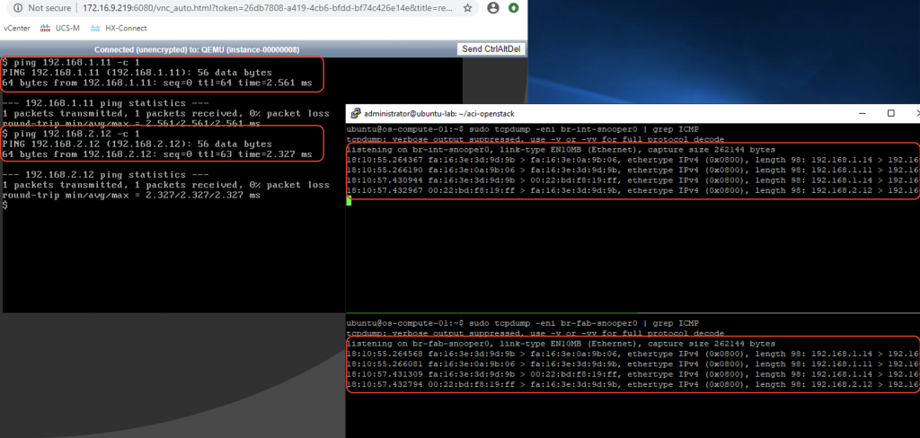
Same procedure as previous scenario applies. This time we can see ICMP traffic on both bridges:
We will keep the ping from vm1 (192.168.1.14) to vm4 (192.168.1.11) going, and let’s do some packet capture on the uplink sub-interface (infra VLAN)
sudo tcpdump -eni ens1f1.300 -w vxlan.pcap
We will use Wireshark to observe the captured traffic, and focus only on UDP traffic.
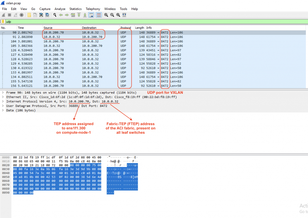
ubuntu@os-compute-01:~$ ip a | grep .300
9: ens1f1.300@ens1f1: <BROADCAST,MULTICAST,UP,LOWER_UP> mtu 1500 qdisc noqueue state UP group default qlen 1000
    inet 10.0.200.70/16 brd 10.0.255.255 scope global dynamic ens1f1.300
Now let’s decode the traffic with UDP port 8472 as VXLAN traffic:
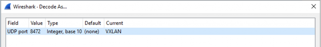
Bam!!! We see the ICMP packet within the VXLAN header sent from the VTEP interfaces on the compute nodes to the Fabric TEP of the ACI:
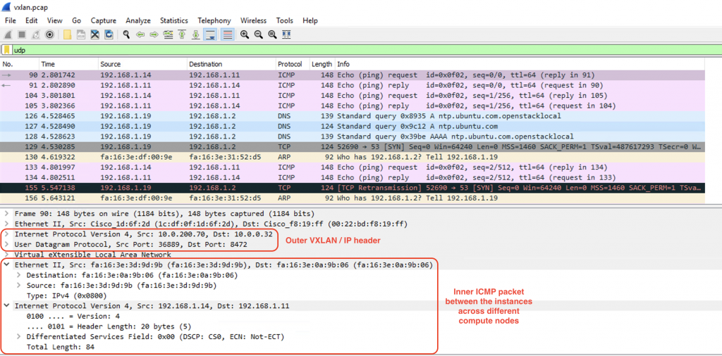
We can do the same process on the other compute node. In short, the ACI will send the ICMP packet encapsulated in VXLAN towards os-compute-02 node. The traffic will get decapsulated and switched/routed by OVS on that node to the correct instances.
That wraps up part 1 of this deep-dive series. In the next part of the series, I’ll be writing in more details about OpFlex-OVS, DHCP and metadata optimization, and external routing from the OpenStack domain through ACI to the outside world. Hope you enjoy the post and stay tuned for the next!